Picture 2: M8017 DLV11-E module
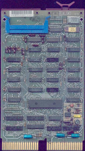
M7940: DLV11 Serial Line Unit
The DLV11 is a dual-height single serial line unit (SLU) that interfaces with asynchronous serial I/O devices. The baud rate can be selected between 50-9600, other settings are: number of data bits, even/odd/no parity, number of stop bits. It can support 20 mA current loop and EIA RS232 interfaces. One of the primary usage of this module is as the console serial port of LSI-11 processors, that have no on-board console ports (such as the LSI-11, LSI-11/2, KDF11-A, KDJ11-A).
Note: jumper means a small piece of wire or a 0-ohm resistor.
Address
The address is set by installing/removing jumpers A3-A12 (near the card-edge connectors)
A12 A11 A10 A9 A8 A7 A6 A5 A4 A3
-   -   -   X   X   X   X   X   X   X   X   X   X   -   -   -
--------------------------------------------------------------
1   1   1   1   1   1   1   1   0   1   1   1   0   X   X   X   jumper setting 0=installed 1=removed
     \  |  /     \  |  /     \  |  /     \  |  /                grouped by three digits, which represent an octal number
        7           7           5           6                   and this octal numbers are part of the address
Thus, the address is 177560The addressing range is 160000-177776, the first two CSR addresses are: 177560 (LSI-11 console), 176500.
Vector
The interrupt vector is configured using jumpers V3-V7 (above the address jumper lines, to the handle-edge of the module).
V7 V6 V5 V4 V3
-   -   -   X   X   X   X   X   X   X   X   X   X   -   -   -
--------------------------------------------------------------
0   0   0   0   0   0   0   0   0   0   1   1   0   X   X   X   jumper setting 0=installed 1=removed
                             \  |  /     \  |  /                grouped by three digits, which represent an octal number
                                0           6                   and this octal numbers are part of the address
Thus, the address is 000060Number of data bits
       NB1            NB2
5      Installed      Installed
6      Removed        Installed
7      Installed      Removed
8      Removed        Removed
Number of stop bits
2SB installed = One stop bit
2SB removed = Two stop bits
Parity
NP removed = No parity bit
NP and PEV installed = Odd parity
NP installed and PEV removed = Even parity
Baud rates
Baud rate   FR3    FR2    FR1    FR0
-------------------------------------
50           I      I      R      I
75           I      I      R      R
110          R      R      R      R
134.5        I      R      I      I
150          R      R      R      I
200          I      R      I      R
300          R      R      I      R
600          I      R      R      I
1200         R      I      R      R
1800         R      I      R      I
2400         I      R      R      R
4800         R      I      I      R
9600         R      I      I      I
External     I      I      I      X
I=installed R=removed X=irrelevantEIA/20 mA interface selection
The module operates with EIA signal levels when the EIA jumper is installed.
If removed, it operates in 20 mA current loop mode.
Active current loop settings:
Transmit: CL4 jumper installed, CL3 resistor installed
Receive:  CL1 jumper installed, CL2 resistor installed
Passive current loop settings:
Transmit:  CL4 jumper removed, CL3 resistor removed
Receive:   CL1 jumper removed, CL2 resistor removed
Cables
For EIA operation, the cable is BC01V-xx or BC05C-xx, for 20 mA current loop it's BC05M.
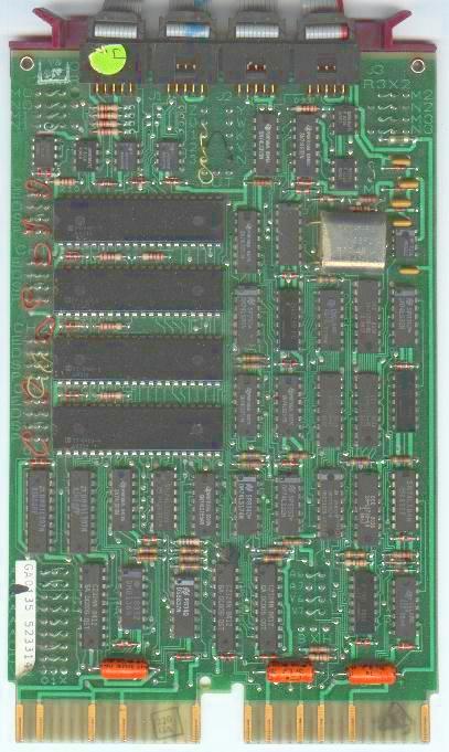
Picture 2: M8017 DLV11-E module
The DLV11-E is an asynchronous serial line interface that connects the qbus to standard serial communication lines. The baud rate is selectable between 50 and 19.200 baud. I also offers full modem control. The DLV11-F is a modified DLV11-E without modem control.
Address
It's configured with jumpers A3-A12, just like on the DLV11.
Vector
Configured with jumpers A3-A12, just like on the DLV11.
Data bits
The number of data bits are configured with jumpers 1 and 2 (next to the 40-pin IC).
       1            2
5      Installed    Installed
6      Removed      Installed
7      Installed    Removed
8      Removed      Removed
Parity control
               P       E
Even parity:   I       R
Odd parity:    I       I
No parity:     R       X
Baud rate
Receive baud rate ins controlled with jumpers R0-R3, transmit is set with T0-T3.
        R3    R2    R1    R0
        T3    T2    T1    T0
50       I     I     I     I
75       I     I     I     R
110      I     I     R     I
134.5    I     I     R     R
150      I     R     I     I
300      I     R     I     R
600      I     R     R     I
1200     I     R     R     R
1800     R     I     I     I
2400     R     I     I     R
3600     R     I     R     R
4800     R     R     I     I
7200     R     R     I     R
9600     R     R     R     I
19200    R     R     R     R
Other jumpers
BG:    Enables break generation
PB:    Enables programmable  baud rate capability
-FB:  When removed, DTR signal is forced on
-FR:  When removed, RTS signal is forced on
RD:    Enables trasnmission of RTS signal
FB:    Enables to force BUSY
C, C1: Enables common speed operation
S, S1:  Enables split speed operation (C, C1 must be removed when S and S1 are inserted)
Cables
The BC05C-xx cable is used with EIA operations.
Picture 3: M8043 DLV11J module
A four-port asynchronous serial line interface. The lines don't have modem control, baud rates are selectable between 150 and 38.400 baud. "Native" interface is EIA, but it can also be used with 20 mA current loop devices using the DLV11-KA adapter.
Addresses
The base address of the module can be selected with jumpers A5-A12.
A12 A11 A10 A9 A8 A7 A6 A5
-   -   -   X   X   X   X   X   X   X   X   -   -   -   -   -
--------------------------------------------------------------
1   1   1   1   1   1   1   1   0   1   0   X   X   X   X   X   jumper setting 0=installed 1=removed
     \  |  /     \  |  /     \  |  /                            grouped by three digits, which represent an octal number
        7           7           5       0                       and this octal numbers are part of the address
Thus, the address is 177500This is Channel 0, the addresses of Channel 1, 2 and 3 (the address here means a base address where the communication registers of the device begin) are offsets of this:
Channel 0:    Base Address
Channel 1:    Base Address + 10
Channel 2:    Base Address + 20
If the base address is 176500, Channel 3 is used as the console SLU.
Vector
The vector is set with jumpers V5-V7.
V7 V6 V5
-   -   -   X   X   X   X   X   X   X   X   X   X   -   -   -
--------------------------------------------------------------
0   0   0   0   0   0   0   0   1   1   1   -   -   -   -   -   jumper setting 0=installed 1=removed
                                \   /   |                       grouped by three digits, which represent an octal number
                                  3     0                       and this octal numbers are part of the address
Thus, the vector is 000300. This is the factory setting. If you jumper pin 1 of V5 to the wire-wrap post "X", console is enabled.Vector alignaments
Channel 0 Receiver:      Base Vector
Channel 1 Receiver:      Base Vector + 10
Channel 2 Receiver:      Base Vector + 20
If the base vector is 300, the interrupt vector of Channel 3 is 60.
Character format
Different character formats (data bits, parity check, stop bits) can be selected for each channel with 4 x 4 three-post jumpers, next to the UART chips. The settings are (X to 0 or 1 means that you mus connect the third post ("X") to the named pin):
Jumper  Function     X to 0   X to 1
-----------------------------------------------------------
D       Data bits    7 bits   8 bits
S       Stop bits    1        2
P       Parity       Enabled  Disabled
E       Parity type  Odd      Even        (a jumper must be installed here, even if parity checking is disabled)
Baud rate
Baud rate is configured with jumpers behind the four BERG connectors on the board. Each Channel has its own wire-wrap post (0,1, 2, 3), you must connect it the post of the desired speed. The jumpers can be daisy-chained. The different speeds are:
Pin label         Baud rate
---------         ---------
    U                 150
    T                 300
    V                 600
    W                1200
    Y                2400
    L                4800
    N                9600
    K               19200
    Z               38400
Cables
BC20N-xx: Direct null-modem cable from the 10-pin
Amp connector to a DB25; for EIA terminals
BC21B-xx: Direct modem cable from 10-pin Amp connector
to DB25; for modems
BC20M-xx: Cable to use between two DLV11Js
Back to the top
Back to "Qbus modules"
Full Table of Contents
Back to the main page
| Created by: Ákos Varga | Last modified: |