Introduction
Jumpers
Diagnostic LEDs
Console ODT
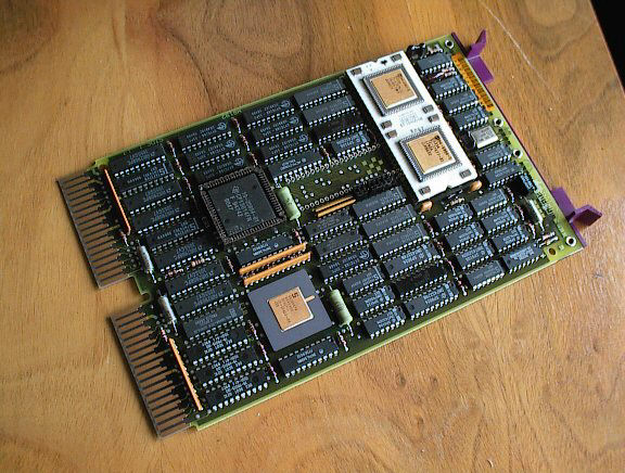
This dual-height module is the heart of LSI-11/73 and embedded systems. It features the DCJ11 chip (two chips, really: ) which was manufactured by Harris Semiconductor. There were different revisons and there were different bugs, so one KDJ11-A might not be equal to another KDJ11-A. example, not all versions were able to work with the FPJ11 floating point processor: the basic M8192 was one of these versions, the M8192-YB and -YC (KDJ11-AB and -AC) worked fine with the FPA (Floating Point Accelerator) chip fitted. (Note: the first "A" behind "KDJ11" is the processor version, the second letter is the revision ID of that particular module. So, the KDJ11-AA and the KDJ11-AC are two versions of the same design, while the KDJ11-B is a totally different one).
The KDJ11-A series features the DCJ11 chip running at 15MHz, 8Kb cache, MicroODT. The module doesn't have any kind of user connectors, i.e. there must be a console SLU on the qbus (at CSR 777560). The KDJ11-A doesn't contain any "user" RAM, system memory (up to 4MB) can be accessed via the qbus. As this CPU is using 22 bits and respecting qbus lines for addressing, a 22-bit backplane is required.
W1: bootstrap address bit 15
W2: bootstrap address bit 14
W3: power-up selection bit 02
W4: bootstrap address bit 13
W5: halt trap bit (halt enable)
W6: bootstrap address bit 12
W7: power-up selection bit 01
W8: wakeup disable
W9: BEVNT recognition
Power up modes:
Mode 0: PC at 24, PS at 26, start execution
W3 installed, W7 installed
Mode 1: MicroODT
W3 installed, W7 removed
Mode 2: Automatic boostrap at 173000
W3 removed, W7 installed
Mode 3: User bootstrap (address selected with W1,2,4,6)
W3 removed, W7 removed
D1: MicroODT mode
D2: Microcode not running (register I/O error)
D3: Memory read/write error
D4: No console SLU found
You can draw conclusions of the state of more LEDs being lightened, for example if D3 (memory acccess) and D4 (no SLU) is on at the same time, it indicates some kind of bus errors, or a memory r/w error without running microcode can be because of an error on the CPU module.
If jumper W5 is installed, and a HALT instruction is executed in kernel mode, or upon power-up (with power-up mode 1 selected), the processor enters ODT (Octal Debugging Technique) mode. The console in this state is un-buffered, communicating half-duplex, so typing ahead while ODT output is displayed is not working. Before accepting any input, the processor executes an INIT, prints a <CR> and an <LF>, displays the content of the PC (Program Counter), prints another <CR> and <LF>, and then the @ prompt. The commands are:
address/
Examine the memory location at address. If no address is given,
it displays the location last entered. If you enter a value after the slash,
and press <CR>, the value is loaded into that location, and the
address is closed. If you hit <LF>, the address is closed, and
the next location is opened.
$n
Opens internal register number n.
addressG
Starts instruction execution at address.
P
Proceeds program execution.
S
Opens the PS.
Back to the top
Back to "Qbus modules"
Full Table of Contents
Back to the main page
| Created by: Ákos Varga | Last modified: |