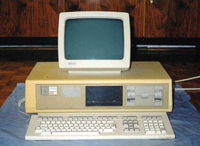
Picture 1: The Digital Professional 350
Picture 1: The Digital Professional 350
History
"Pro" hardware basics
Operating systems
Enclosure
The color monitor cable
Options
Startup diagnostics, error codes
The Professional was designed in 1981-82, as a competitor of the then-new IBM PC. DEC felt that personal computers are the way to go, but didn't like the idea of just cloning IBM's machine (DEC OEM'd PC's made by other companies (like Tandon) for a long time before they designed their first 100% IBM PC-compatible machine). They introduced three different families at the same time: one was the DECmate II (PC27X), based on the PDP-8 instruction set and program library, one was the Rainbow 100 (PC100), a dual system with a Zilog Z80 and an Intel i8088 processor, which was the closest thing to a PC, running an altered version of MS-DOS, and the Professional 300 (PC300), based on the LSI-11 technology. The idea was nice, and the machines were well-enginered, but the market choosed IBM. But apart from the relatively small volumes, when I say "well-engineered", I mean that many Professionals (and Rainbows, and DECmates...) are still functional, in use...
As said before, the "Pro" was based on the PDP-11 architecture. The three different models used PDP-11 microprocessors: the Professiona 325 and 350 was based on the F-11 chipset used in LSI-11/23 and MicroPDP-11/23 systems, the Professional 380 used the same J-11 chip that can be found in LSI-11/73, MicroPDP-11/53, MicroPDP-11/83, MicroPDP-11/93, etc systems. The instruction set is the same, but unlike the "normal" -11's, the Pro family doesn't have a general system expansion bus, like the Unibus or the qbus, which had enormous support at the time. Instead, the Pro has an own bus called the CTI bus. Unfortunately not much has been developed for this interconnect, so that it doesn't cut into sales of "real" PDP-11 systems (no tape drives, no support for large disks, more terminals, etc). On the other hand, it was a very nice graphic workstation for the time, intended for single user tasks (although there were some Unices available), with monochrome or color bitmap graphics.
The three different Professional models:
DEC had made another mistake: instead of a normal PDP-11 operating system, they introduced something new, called P/OS (Professional Operating System, dubbed as "Piece Of Sh*t" by many), which was a menu-oriented character-graphic version of RSX-11M. It's not very nice, and it's slow, but let's not forget that tha machine was aimed at office workers, not programmers and computer specialists. Basically, you're dropped into a menu system upon boot, where you must navigate with the arrows, hotkeys and function keys. "Power users" loved the "P/OS Toolkit" extension, which installed a DCL shell (from then on you can use the good old command line utilities). There were office suites and different programming languages available for P/OS.
Not much later DEC also introduced RT-11 for the Pro, as a "real -11 way" alternative.
VenturCom sold a UNIX-clone called Venix for the Pro 350 and 380, these are now in the public domain (as is P/OS).
The three "almost-PC" form DEC look very much alike, in fact the DECmate II and the Pro share the same enclosure, while the Rainbow has a somewhat smaller box. The machines were also sold in standing tower configurations, which are in fact just emtly shelves which bury the desktop enclosure. Be warned: these boxes look like PC's, but they're much heavier (especially the HD and the PSU)! The back of the standing tower can be opened and the "normal" enclosure can be pulled out.
The desktop box has a nice feature which I like very much: it can be taken apart without using a screwdriver! You just have to know the right moves: first, pull the two little levers onthe left and right of the enclosure (just below the recess) into the middle position. Then, carefully lift the upper part.
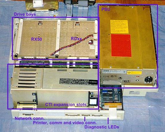
Picture 2: The Pro enclosure without the top part, with
disk and motherboard pulled out
Then, the drives can be pulled out after you disconnected their cables. There's a little notch beneath the dirve bays which needs to be pushed upwards to let the drives slide out. Disconnect the cable that goed out from the back of the PSU to the motherboard. Unscrew all screws that hold the motherboard+expansion cardcage to the back of the drive bays (this can be done with a coin if the plastic thingies on the screws are still there (they tend to fall apart)). The two small covering sheets on the cardcage can be removed after you untighten another few screws. Remove all cables that come out form the cards. Pull the plastic levers on the bottom of the cards, and turn them 90 degrees. The cards can now be removed (don't force it, see if it stucks). Carefully pull out the motherboard.
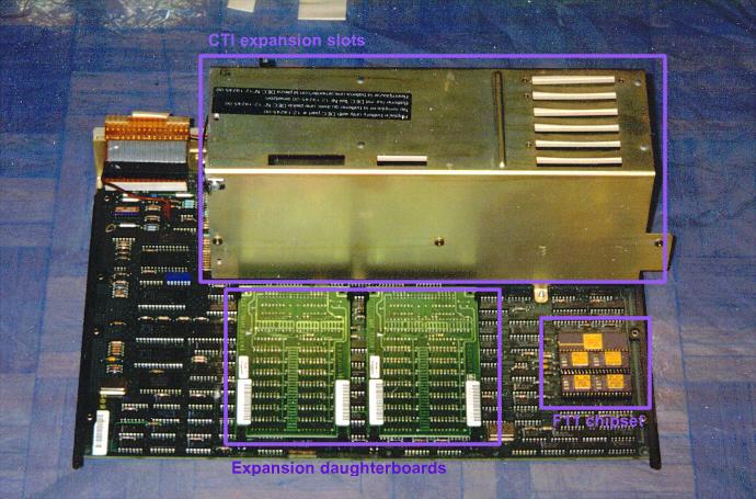
Picture 3: The motherboard of the Professional 350
The photo above depicts a Pro 350, the Pro 380 motherboard looks different. Note the F-11 chipset on the right and the two memory daughterboards in the middle! The latter can be removed, after you un-snap the small levers that hold them in place. (Btw, the 128 KB memory boards of the 350 can be replaced with the 512 kB boards of a 380). On the back of the motherboard/cardcage combo there's the back panel of the machine. Here is the communication port (DB25), the printer port (DB9, this can be used as a diagnostic console with a BCC08 cable) and the video signal connector (DB15). On the left you can see another DB15 port which is for an AUI ethernet connection. The DECNA ethernet option must be installed to use thsi interface, it's useless without it! There are also some diagnostic LEDs there. All connectors are labelled.
The monochrome monitor for the Pro was the VR201 tube, which was also used on the VT240. The cable is a straight-through 15-pin DB15-DB15 cable, the LK201 (or LK401) keyboard is attached to the small connector on the back of the monitor.
The color monitor is another business: it needs an RGB sync-on-green monitor with a 15 KHz video signal - an old Commodore/Phillips (and most of the RGB monitors used on older microcomputers) tube will do the job nicely! (Remember that color graphics was an option, which needs to be installed to use a color monitor!). The standard color CRT was the VR241. The cable is a DB15 on one end, which goes into a little box. Out come three BNC's (R, G and B for the monitor), and a 4-pin phone-plug-like connector for the keyboard.
Professional 380 color monitor cable pinout:
Pin:
Description:
1,2,3,4,5,6
Ground
7,8
+12 Volts
9
Blue
10
Green
11
Red
12
Monochrome
13
Monitor Present
14
Keyboard transmit
15
Keyboard receive
Keyboard:
1 Data Send (via J1, pin 15) Serial line
for output from the system box to the keyboard
2 +12 Vdc (output of operational voltage to
the keyboard (from J1 pins 7 and 8))
3 Ground (from J1, pins 5,6,13) Operational
voltage ground.
4 Data Receive (via J1, pin 14) Serial
line for input from the system box.
Options (modules, system parts, etc) of the Pro have six-digit codes, which are quite cryptic (okay, some of them have option names too, but...). These device codes are used in error messages displayed at power-up. Special thanks to Megan B. Gentry for this list!
ID
Device Name
000001
8 slot CTI backplane
000002
7 slot CTI backplane
000003
6 slot CTI backplane
000004
5 slot CTI backplane
000005
4 slot CTI backplane
000006
3 slot CTI backplane
000007
2 slot CTI backplane
000010
1 slot CTI backplane
000011
CT100 BASE processor (11/23, mmu)
000012
Floating point processor (FPP)
010012
PC352 FPP (integrated within J11)
000013
VT100 keyboard control
000014
LK200 keyboard control
000015
VT100 keyboard
000016
LK200 keyboard
000017
CT100 printer port
000020
CT100 speaker control
000021
CT100 communications port
000023
CT100 time/date clock
000024
CT100 nonvolatile RAM (NVR)
000025
CT100 interrupt controller
000026
CT100 DIAG/ROM version 1.0 (first release)
010026
CT100 DIAG/ROM version 2.0 (IVIS)
000027
CT100 maintenance console port
000030
CT100 option present register
000031
CT100 serial number ROM
000032
CT100 monitor attachment
000033
CT100 primary RAM
000034
CTI Bus option RAM (256Kbytes)
000035
PC352 base processor (J11, MNU)
000036
PC352 interrupt controller (integrated inside I/O gate array)
000037
PC352 base system ROM version 1.0 (1st release)
000040
CT100 DMA test module
000041
DTC11-A CTI Telephone Management Service (TMS)
000042
DECNA CTI Ethernet Controller
000043
CTI Z80/CPM option
000044
CTI T-11 softcard
000045
IVIS base module set
000046
IDLDR IEEE option (LDP)
000047
KANJI font module
000050
PC352 bit map video base module
000051
DRC11-AA CTI Parallel Interface
000052
DLC11-AA CTI Serial Interface
000053
ARC11-AA CTI Analogue Interface
000054
MRC11-AA CTI Rom option (LDP)
000060
DECtouch module (DTM)
000064
CTI Quad serial line option
000401
CTI 5.25" Winchester disk controller
001002
CTI Professional 350 Bus video bit map controller
001403
CTI Professional 350 extended bitmap (color option)
002004
CTI RX50 5.25" floppy diskette controller
002405
CTI fast serial line
003006
IVIS system module (no ROM)
010001
Tempest keyboard (shielded)
010050
PC352 bit map video extension
011002
IVIS bit map base module
011403
IVIS bit map video extension
030050
PC352 bit map extension and color map
Startup diagnostics, error codes
Upon power-up, the Pro executes a sequence of system diagnostic tests. If an error occurs, error codes are displayed on the monitor, or if no graphic head is available, on LEDs on the back of the enclosure. This diagnostics are quite nice: the system displays a schematic picture of the computer, showing some numbers (including the option number of the module) and highlighting the parts of the machine which have problems (i.e. which cards in the cardcage have failures, the floppy, if there's an non-bootable disk in the drive, etc). Sometimes the error is fatal and the startup sequence stops, sometimes it continues after a few seconds. In normal cases a big |d|i|g|i|t|a|l| logo is displayed, and the operating system boots.
The error codes:
Code Problem area
Corrective Action
000100 P/OS keyboard handler 1: Check cables
and connections
2: Reseat option modules in card cage.
3: Reset all IC's in sockets on system module.
5: Replace system module
6: Reload Operating system.
000200 Terminal driver
?
000300 Executive/general
If error occured on first access of RX or RD subsystem, check that subsystem
is in order:
1: Check cables and reseat controller in card cage
2: Replace Drive
3: Replace RX or RD subsystem controller
If no error is found on first access of mass storage, goto 000200 for corrective
action.
000400 System startup processing
000500 Terminal driver (video and printer port)
Second line Error Codes
0000 IOT in system state
000001 Stack overflow or cannot install task CBOOT
000002 Trace Trap or breakpoint or cannot spawn task CBOOT
000003 Illegal instruction trap or cannot spawn task CBOOT
000004 Odd address or other trap to 4
000005 Segment fault
000006 A task on P/OS without a parent aborted
000007 EMT trap or required file not found
000010 TRAP trap
There's not much you can do in case of a hardware problem, apart from pulling out and reseating the cards, IC's and connectors (this helped me a couple of times, can it be, that the CTI mechanical design is not that good after all?).
Back to the top
Back to the main page
| Created by: Ákos Varga | Last modified: |